An Introduction to UML
Author Note: This was originally posted on linux.com in 2008. I am replicating it here for posterity.
When you’re designing and developing new software systems, it is often hard to see how all the pieces are suppose to fit together. Unified Modeling Language (UML) is one tool that allow developers and architects to ease the process and create a big picture before committing to a particular technology.
UML is simply a language, as its name suggests. It can be used, along with a working development methodology, to aid in designing and describing a software system. The process is called modeling. UML allows architects, developers, management, testers, designers, and users to come together and create a software model in an abstract fashion. This abstraction is what makes software modeling useful, as the people involved in creating software come from different backgrounds and have different skills; the model, described in UML, gives them all a common picture of the system. This common picture provides a base of understanding for the entire project; it produces a nomenclature for the project, a viable way to group tasks and set deadlines, and a way to have meaningful discussions between contributors without becoming lost in the details.
UML models are diagrams of three primary types: structural, behavioral, and interaction. Generally, structural diagrams define the underlying software system (the code), behavioral diagrams describe what happens in the system under certain conditions, and interaction diagrams explain control flow. They are a subset of behavioral diagrams. Various sources classify diagrams differently — they have different names and different orders of importance — but the UML 2.0 specification is the authority on how they should be classified. Here is a short list of some of the diagram types:
Structural diagrams:
- Class diagram – A class diagram describes classes, packages, and their relationships to each other. Classes allow developers to organize code into logical pieces that share resources. Packages allow classes to be logically grouped.
- Component diagram – Illustrates how all of the structural components of a system interact.
- Deployment diagram – Provides a map of how the system will look once it is installed. Includes hardware and system specifics.
- Composite structure diagram – Models the internal structure of a class and the collaborations the structure makes possible.
Behavioral diagrams:
- Use case diagram – Model how users interact with the underlying system.
- Activity diagram – Models the overall control flow of the system.
- Statechart diagram – Models the state of the system at particular points of execution.
Interaction diagrams:
- Sequence diagram – Models interaction among actors, objects, and other objects. It is basically a time-line.
- Collaboration diagram – Model the interactions and relationships between objects.
- Communication diagram – Models sequenced message interactions between objects.
You can create UML diagrams using a myriad of tools and methods, from simple pencil and paper to the nice but expensive Rational Rose. Of all the open source options available, I am partial to Umbrello; it supports all of the diagrams mentioned above and several code export options: ActionScript, ADA, C++, Java, JavaScript, PERL, PHP, Python, Ruby, SQL, and more. It’s easy to use and allows multiple diagrams to be contained in a single XML file, having diagrams for multiple projects is allowed but could be confusing and should be avoided if possible.
A quick look at prototyping with UML
For many projects, most of the diagrams are not useful . The two most important diagrams are the class and use case diagrams.

Class diagrams allow developers to prototype systems without worrying about anything other than the design. The following image is a small UML class diagram from Umbrello. Notice that there is a package, or namespace, called Test_Namespace. Attached to the package (“contained” in UML speak) is a class named Test_Class. The class node allows markup for attributes (properties) and operations (functions/methods). Attributes have datatypes (strings, integer numbers, floating point numbers, etc.), scope (are they constant or can they be changed), and visibility (can other classes have access or they internal) settings. Operations have types, parameters (values passed to them from the caller), visibility, and scope. Every type of construct available in modern object-oriented programming languages can be modeled with UML. This is not to say that UML is only for object oriented languages, the class diagram however is.
Models also present a visual map of how classes interact and what dependencies they have to other classes and objects. This image shows that class Another_Class has an object named tcobj that is of type Text_Class. This type of visual display is useful in minimizing coupling (see Law of Demeter) and aids in the refactoring process.
Another added feature of UML is the option to document UML itself. When Umbrello exports the UML as code, the documentation is also exported in the selected language’s automated document format. This is a nice feature for many software developers who document only when they have time, which is usually never. In-line documentation also benefits anybody that may ever read the code; too often this kind of documentation is all a maintaining developer may have to go on.
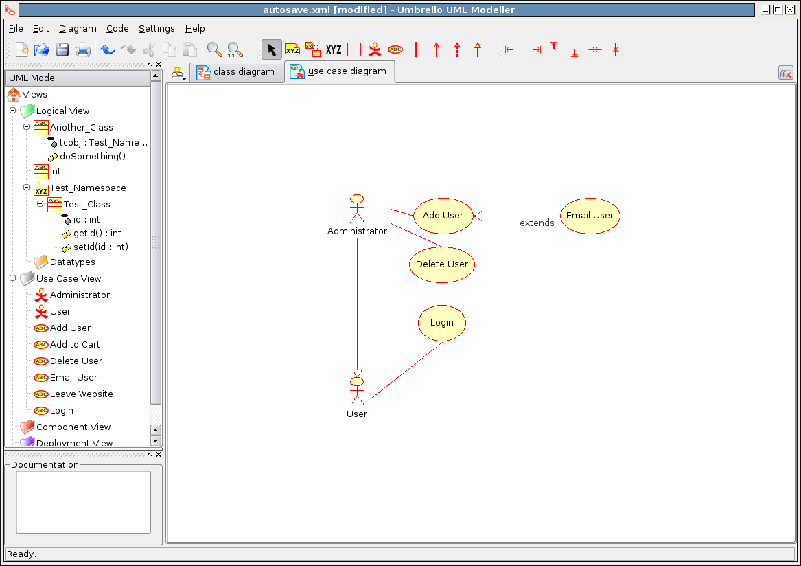
Use case diagrams are useful when a developer is designing moderate to complex interfaces, among other action-related processes. A typical use case diagram involves actors and use cases. Actors, defined by stick people, are users, machines, or anything that does something. Use cases are typically actions that an actor performs, defined by circles.
Take a look at the following use case diagram. There are two actors, Administrator and User, and four actions, Add User, Delete User, Login, and Email User. Simple lines connect actors to use cases. Special types of lines connect actions to other actions, as you can see with the Add User and Email User actions. The Add User case extends the Email User case — this means that when a user is added the user is also emailed. The types of arrows connecting actors and use cases are also significant. See the “implements” line (designated by a filled arrow on one end) between the two actors? It shows that the Administrator is also a User.
Use case diagrams allow modelers to map out all the possible scenarios that can occur while the system is in use. The process of thinking through scenarios can drastically reduce the missteps and assumptions that developers may make when developing. Use case diagrams are also useful when preforming usability testing, they can be virtually linked to actual use cases. Use case diagrams and use cases are not the same; use case diagrams can serve as a map to use cases.
A few final things to keep in mind: Don’t waste your time modeling simple systems; the return is usually not worth the time. Don’t spend too much time modeling any systems; you will never think of everything. My rule of thumb is never formally model a project if it will take a developer less than a day to complete, and stop modeling once all of the initial requirements are met — do not add complexity and additional requirements when modeling. And, lest you feel overwhelmed by technology, you do not need any software to model software — a whiteboard works just fine.
While modeling software is useful, it will not solve all design issues. Smart people and a good methodology are a must. But if used correctly, UML and the modeling process can help improve quality, completeness, and scalability and reduce production time in many software projects.